Compressed Air Leak Detection During Operation

Practical Leak Detection, Prioritization, and Validation in Compressed Air Systems

1. Why Compressed Air Leaks Should Be Detected and Repaired

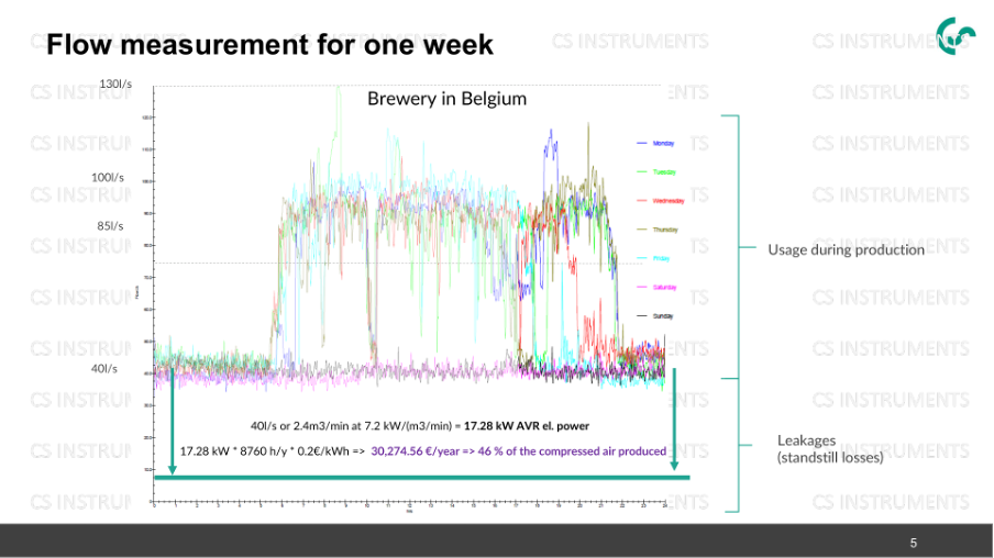
Compressed air leaks do not result in a one-time loss, but rather permanently increase air demand. The additional air must be generated by the compressor, dried, filtered, and distributed throughout the system. This leads to increased electricity consumption, longer operating times, pressure losses, and higher maintenance costs. Base load is particularly critical: High consumption outside of production often indicates leaks or unnecessary air purges.

Leak detection should therefore not be viewed as an isolated maintenance task, but rather as a demand-side measure. Only once consumption, base load, and the proportion of air lost to leaks have been reduced can the supply side—including compressor control, pressure band, and specific power—be meaningfully evaluated.

asset_image

Example of a weekly measurement: Base load and idle losses become visible and can be evaluated from an economic perspective.

2. Why Ultrasound Works Despite Production Noise

In industrial leak detection, distinguishing between audible sound and ultrasound is crucial. Most production noises fall within the audible, low-frequency range. Leaks in compressed air and gas lines generate broadband turbulence with high-frequency sound components at small leak openings. Large leaks often generate additional audible sound; however, in production environments, this is frequently masked by machine noise.

Frequency RangeDescriptionSignificance in Industry
Audible sound (approx. 20 Hz to 20 kHz)Frequency range that can be perceived by the human ear.Noises from machines, motors, fans, and speech typically fall within this range.
Ultrasound (> 20 kHz)A range of sound inaudible to humans.Leaks, partial electrical discharges, and other high-frequency events often generate ultrasonic components.
Target frequency windowFor the measurement of a selected frequency range within the ultrasonic spectrum.Enables the suppression of interference signals and the targeted detection of relevant ultrasonic sources.

The ultrasonic sound generated by a leak is not caused by the gas itself, but by the turbulence that occurs as the gas escapes. The pressure difference, leak geometry, and the shape of the exit opening determine the sound intensity and the frequency spectrum of the generated ultrasonic waves.

Higher frequencies offer better spatial resolution due to their shorter wavelength. However, as the frequency increases, atmospheric attenuation also increases, thereby reducing the achievable detection range. The choice of measurement frequency therefore represents a trade-off between resolution, range, and interference suppression. In many industrial applications, a frequency range around 40 kHz has proven to be favorable. In environments with interference, however, a different frequency window may yield better results.

In-Depth:Leak Detection Despite Interference Sources and FFT

3. Typical measurement locations during operation

The advantage of the ultrasound camera lies in its combination of distance measurement and visual identification. Leaks can be located during operation while the system is running under actual pressure and load conditions. This also reveals leak points that would not occur if the system were shut down.

  • Pipes on plant ceilings: Inspection from a safe distance, without a ladder or aerial work platform, provided the leak is sufficiently severe.
  • Machines and pneumatic systems: Systematically check valves, cylinders, hoses, couplings, filters, regulators, and maintenance units for leaks.
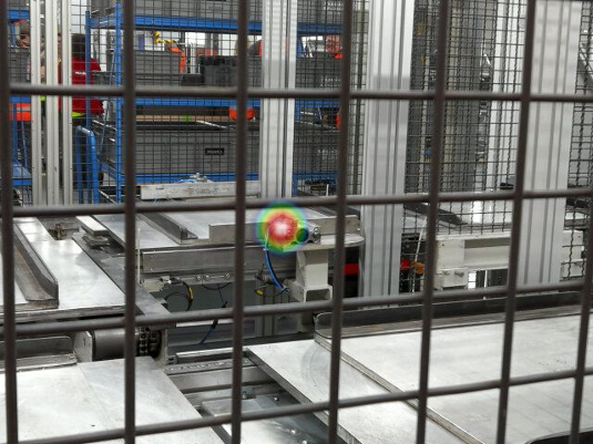
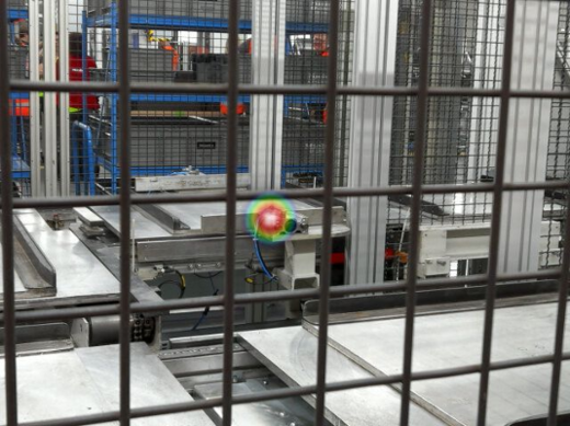
  • Protective grilles and robotic cells: With acoustically transparent grilles, the sound source can also be located behind the barrier.
  • Hazard and logistics areas: Measurements can be taken outside the range of photoelectric sensors, robotic cells, or forklift travel paths.
  • Hard-to-reach areas of the facility: The ultrasound camera enables leak detection even at points of measurement with limited access. This requires sound to travel as directly as possible between the leak location and the camera.
Compressed air leak in the warehouse ceiling located using an ultrasonic cameraUltrasonic camera locates leak behind protective grille
Example: Hard-to-reach plant ceiling: The hotspot indicates an ultrasonic source on a compressed air line.Example: Protective grilles can be largely acoustically transparent to ultrasound. The hotspot remains visible when the sound waves pass through the grille.

4. Measurement Through Protective Grilles and Open Areas

Wire mesh and protective fences are often largely permeable to ultrasonic waves. In contrast, solid surfaces such as Plexiglas, sheet metal, concrete, glass, or smooth machine casings act as strong reflectors. For reliable leak detection, there should therefore be a direct sound path between the leak location and the microphone array.

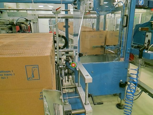
In the example shown, this direct sound path is made possible by an open gap in the Plexiglas enclosure. The solid enclosure is not in the sound path and therefore does not affect the measurement.

Leak detection on a packaging machine via an open gap instead of through Plexiglas

Packaging machine with Plexiglas enclosure: The measurement is taken through an open gap with a direct sound path to the leak location.

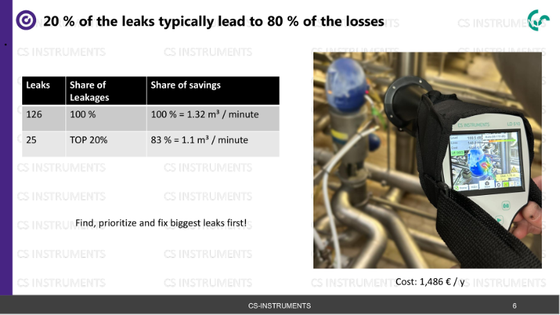
5. Prioritize leaks: Fix the biggest losses first

The volume of water lost and the resulting costs are the primary factors in determining priorities. Since large leaks can mask the sound of smaller leaks, they should be documented and repaired first. A follow-up inspection often reveals additional leaks that were previously hidden.

Typically, 20 percent of leaks account for 80 percent of losses

Prioritization logic: A small proportion of leaks often accounts for the largest share of losses. Repair large, dominant leaks first.

6. Document the repair and validate the consumption

Leak detection alone does not save energy. Savings are achieved only through repair, follow-up, and verification of the new operating condition. The detected leaks should be documented with their location, a photo, leak rate, cost estimate, repair instructions, and status. Consumption is then compared before and after the corrective action.

StepMeasurement/Documentation ContentBenefits
1. Measure consumptionBase load, load profiles, peak load, pressure levelIdentify the initial condition and the proportion of leakage.
2. Locate leaksHotspot, component, image, distance, estimated leakage rateIdentify specific repairable leak points.
3. PrioritizeLeakage flow rate, costs, accessibility, safety considerationsFocus resources on areas with the greatest potential for savings.
4. RepairWork order, replacement part, status, responsibilityA detected issue is turned into an implemented measure.
5. ValidateExamine consumption before and after repair, considering base load and peak load separatelyVerify savings and establish a new operational baseline.