Compressed air leak detection despite ultrasonic interference

Frequency windows, signal-to-noise ratio and operational disturbances in automated systems

Production noise in the audible range is effectively filtered out by the ultrasound camera and does not interfere with leak detection – reliable measurements can therefore be taken even in noisy halls. In many production environments, there is also little or no interfering ultrasonic noise; in which case leak detection can be carried out immediately. In some areas, however, there are stronger sources of ultrasonic interference. For these more challenging situations, there are tried-and-tested methods for better managing the interference and still reliably locating leaks. This guide shows you how.

1. Why not every ultrasonic source is a leak

Many production noises fall within the audible range and have only a limited impact on ultrasonic leak detection. Even in areas of a plant with moderate sources of ultrasonic interference, medium-sized and larger compressed air leaks can often be reliably detected during operation – particularly from short to medium measurement distances.

However, it is important to note that not every visible ultrasonic source is automatically a leak. In automated systems, pneumatic vents, valves, machine movements, friction processes or reflections can also generate ultrasonic signals. The decisive factor is whether these sources of interference lie within the same frequency window as the leakage signal being sought. An ultrasound camera localises sound sources within a defined frequency range and makes suspicious hotspots visible. The assessment is then carried out in the context of the system – for example, taking into account pressurised components, cycle times, viewing angles, the frequency spectrum, measurement distance and the stability of the display.

In compressed air systems, medium and large leaks in particular generally offer the greatest potential for savings. At the same time, they represent strong ultrasonic sources and should usually be repaired first. In technical gases and vacuum applications, however, even smaller leaks can be highly significant, for example for quality, process or safety reasons. When detecting very small leaks in acoustically challenging environments, physical factors such as sound attenuation, reflections and the signal-to-noise ratio at the measurement site play a greater role.

To realise the full potential of ultrasonic camera technology, we recommend a tailored measurement strategy, the correct choice of equipment and a reliable interpretation of the measurement results. We would be happy to advise you on which leak detector is best suited to your production environment and to support you with online or on-site training to ensure optimal use.

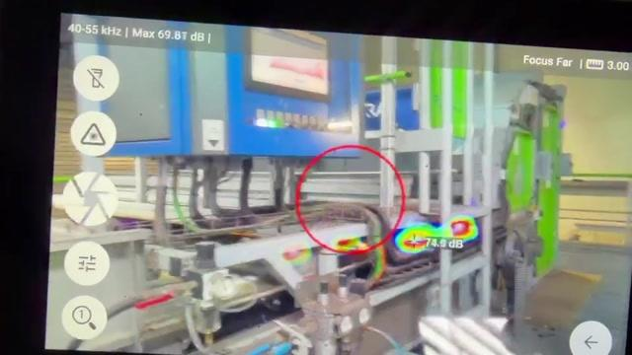
Ultrasonic camera identifies hotspots on an automated system with potential sources of interference

Practical example from an automated plant: Multiple hotspots can arise due to process movements, pneumatic systems or reflections. Relevant leaks must be attributed to pressurised components.

The better the signal-to-noise ratio in the relevant frequency window, the more effectively and from a greater distance leaks can be detected. In a quiet ultrasonic environment, it is therefore physically possible to detect significantly smaller leaks than in areas with strong sources of interference.

2. Specific measures to be taken in the event of faults and their physical effects

Check for hotspots on the pressurised component
A hotspot should first be verified on the system. A genuine leak occurs at a pressurised point, such as a screw connection, coupling, pipe, fitting, seal or valve. If, on the other hand, a hotspot is indicated on a wall, sheet metal, protective screen or the floor, it may be a reflection.

Physical background: Ultrasound is strongly reflected off hard surfaces. The camera may then appear to indicate a source on the reflective surface, even though the actual sound source is located elsewhere.

Action: Change the viewing angle and take another measurement. A genuine leak remains consistently visible on the component. A reflection moves, changes position or disappears.

Reduce the measurement distance
If the leak signal is too weak compared to the background ultrasound, the distance to the suspected source should be reduced, for example to around 1 m or even closer at close range.

Physical background: The sound pressure from a source decreases with increasing distance. If the distance to the leak is reduced, the sound pressure level measured at the microphone array increases. At the same time, more distant sources of interference become relatively less significant. This improves the signal-to-noise ratio.

Action: Move closer to the pressurised component and scan the area again. This is often crucial, particularly in the case of weak leaks.

Check the frequency spectrum and shift the frequency window
The FFT display helps to identify dominant interference frequencies in the measurement environment. If strong ultrasonic components lie within the currently selected frequency window, the display may become erratic or mask a leakage signal.

Physical background: Leaks generally generate broadband ultrasound. Interference sources, on the other hand, may dominate specific frequency ranges. If the active frequency window is shifted so that strong interference components lie outside the window, the separation between the leak and the interference improves.

Action: Shift the frequency window to a range with less interference. In practice, it is often advisable to test higher frequency ranges. It should be noted, however, that higher ultrasonic frequencies are more strongly attenuated by air. For greater distances, lower or mid-range frequencies may therefore be preferable.

Adjusting sensitivity, threshold and dynamic range
With the UltraCam LD 500/510, the user can adjust the acoustic sensitivity and threshold to suit the environment. The threshold determines the sound pressure level at which an acoustic event is displayed as a visible hotspot. If the threshold is increased or the sensitivity reduced, weak background signals are suppressed. The ultrasonic image appears clearer and is easier to interpret. The LeakCam 600 also assists the user by automatically adjusting the dynamic range of the ultrasonic image. In Auto mode, the system analyses the level distribution in the ultrasonic image and adjusts the display to produce the clearest possible image. In manual mode, the user can adjust the threshold themselves to suit local conditions.

Physical background: Reducing the sensitivity or setting a higher threshold does not improve the actual leak signal, but rather suppresses weaker signals. This makes the display more stable, but very small or distant leaks may no longer be visible under certain circumstances.

Action: In the event of strong interference, increase the threshold or reduce the sensitivity. When searching for micro-leaks, minimise ambient noise, move closer to the source, select a clean frequency window and increase the sensitivity again accordingly.

Eliminate dominant noise sources first
Significant leaks, open vent pipes, ultrasonic baths, fans, blowers or other dominant sources can mask weaker leaks.

Physical background: Where there are several ultrasonic sources within the measuring range, the strongest source dominates the display. As a result, smaller leaks may disappear from the ultrasonic image or cannot be reliably assessed.

Action: First mark, document, rectify or temporarily switch off dominant sources. Then scan the area again. Weaker leaks often only become visible once the strongest sources have been removed.

Monitor the process status
In automated systems, many ultrasonic sources occur only intermittently. Examples include pneumatic cycling, valves, cylinders, screwdriving processes, presses, grinding, drilling, milling or cycled venting.

Physical background: A genuine leak usually generates a relatively stable, reproducible ultrasonic signal as long as pressure is applied. Process-related sources, on the other hand, frequently occur in synchronisation with movements, cycles or processing steps.

Action: Check whether the hotspot is permanently visible or only occurs during a specific process step. If necessary, repeat the measurement during a standstill phase or non-production period.

Temporarily increase the system pressure
If permitted by the process, the system pressure can be temporarily increased to the maximum permissible operating pressure.

Physical principle: As the differential pressure increases, the volume flow escaping from a leak generally increases. This causes the ultrasonic level generated to rise, making the leak easier to detect.

Action: Increase the pressure only within the permissible operating limits and then take another measurement. This measure is particularly helpful for small leaks or those that are barely detectable.

Carry out the measurement during quiet process phases
If reliable localisation is not possible despite optimised settings and a reduced measurement distance, the measurement should be repeated during a quieter phase.

Physical background: The smallest detectable leak is largely limited by the signal-to-noise ratio. The lower the background ultrasonic noise, the weaker the leak signals that can be detected.

Action: Where possible, search for micro-leaks during non-production periods, downtime or when sources of interference are switched off.

3. Common sources of interference, how to identify them and appropriate measures

Source of interferenceHow can you recognise them?Practical countermeasures
Pneumatic valves and cylindersShort, cycled ultrasonic pulses. The hotspot appears periodically or shifts in time with the movement cycle.Monitor the process cycle, check the connections specifically and, if necessary, take further measurements during a shutdown.
Blow-off nozzles and open compressed air usageVery strong, stable or pulsed ultrasonic source. Other leaks may disappear from the image.If possible, temporarily switch them off or mark them as regular consumers. Then scan the area again.
Other strong leaks in the vicinityA dominant leak can mask smaller sources.Document or rectify major leaks first, then measure again.
Conveyor belts, presses, friction and contact pointsBroadband or pulsed ultrasonic components, often dependent on movement or contact.Carefully inspect hotspots outside pressure-bearing components, take the process conditions into account and adjust the frequency window.
Grinding, drilling, milling and other friction processesFrequently broadband, continuous or pulsed ultrasonic signals caused by tool contact, chip formation or material friction.Carry out measurements outside the machining process where possible, or shift the frequency window to a range with less interference
Electric screwdrivers and cycled toolsShort ultrasonic pulses synchronised with the tightening or operating cycle.Synchronise the hotspot with the tool’s operation and check again when the tool is at a standstill.
Frequency converters, power electronics and electric drivesFrequency-dependent or stable hotspots on electrical components, not at points under pressure.Check the system context, analyse the FFT and do not automatically assume the source is a compressed air leak.
Electrical discharges / corona effectsUltrasonic signals on electrical components, often unrelated to compressed air lines.Observe safety guidelines, investigate the source in the context of the system and do not assume it is a compressed air leak.
Lamps, luminaires and electronic ballastsHotspot on a luminaire or electronic component, often stationary and independent of compressed air components.Switch off the lighting on a trial basis, where permitted, and check the frequency spectrum.
Ultrasonic baths and ultrasonic cleaning systemsVery strong technical ultrasonic source, often with dominant frequency components.If possible, switch them off, increase the distance or carry out the measurement whilst the equipment is not in operation.
Fans, blowers and strong air currentsBroadband ultrasound caused by turbulence, bearing noise or blade movement.Identify the source of the flow, change the viewing angle, adjust the frequency window and carry out targeted testing of pressure-bearing components.
Fluids with high flow velocity in pipesHotspots on pipes, valves, orifices or changes in cross-section, without a discernible point of escape.Take into account the pipework layout, fittings and process conditions. Verify the actual point of escape before classifying the hotspot as a leak.
Sound-reflective surfaces and reflectionsA hotspot appears on the floor, wall, sheet metal, cladding, protective screen or Plexiglas.Change the viewing angle or distance. A genuine leak remains stable on the component, whilst a reflection moves or disappears.

4. Summary

Reliable leak detection is not achieved solely through maximum instrument sensitivity, but through the best possible separation between the leak signal and background noise. The key parameters are measurement distance, angle of view, frequency window, threshold, sensitivity, process conditions and the reduction of dominant ultrasonic sources.
A stable ultrasonic image is helpful, but must not be confused with higher physical detection performance. If sensitivity is reduced or the threshold is increased, small leaks may be masked. 
For micro-leaks, the following therefore applies: measure as close as possible, reduce sources of interference, select a clean frequency window and carry out the measurement in as quiet an environment as possible.