Detecting vacuum leaks using ultrasound

Special case: vacuum – inflow of ambient air, weaker signals and measurement strategy

1. How are ultrasonic signals generated by vacuum leaks?

In the case of compressed air and gas leaks, the medium escapes from the system. In the case of a vacuum, the flow direction is reversed: ambient air flows into the system. Here too, turbulent flows can occur at small openings, seal seats, flanges or valves, generating ultrasonic signals.

The ultrasound camera therefore does not detect ‘vacuum’ as a medium, but rather the acoustic energy of the inflowing air at the leak point. The method remains passive and requires no test gas. However, the focus of the assessment shifts: the primary considerations are vacuum stability, pump load, process quality, evacuation time and the risk of contamination.

2. Difference from compressed air leaks

Aspectcompressed air leakVacuum leakage
flow directionThe medium flows out of the system.Ambient air flows into the system.
Typical assessmentEnergy loss, base load, compressor work, media costs.Vacuum stability, pump load, evacuation time, process quality, contamination.
Acoustic signalOften steady and clear when pressure is sufficient.Often weaker and more dependent on geometry, distance and access.
Measurement strategyStart from a distance, tackling large leaks first, then moving closer to smaller sources.Short distance, quiet frequency range, multiple angles of view and targeted inspection of sealed areas.

3. Why vacuum is often more challenging

As the absolute pressure difference in many vacuum applications is lower than in compressed air networks, a weaker ultrasonic signal is often generated at the leak point. Furthermore, the geometry of the leak has a significant influence on sound emission. Small gaps or seal seats often produce less directional ultrasound than nozzle-like outlet openings in compressed air applications.

For practical leak detection, short measurement distances, low-interference frequency windows, stable process conditions and measurements from multiple angles are particularly crucial. In the case of micro-leaks, it is usually not the theoretical sensitivity of the system that is the limiting factor, but rather the signal-to-noise ratio at the microphone array. The decisive factor is whether the leak signal stands out sufficiently from the background ultrasound.

4. Common points of leakage

  • Seal seats and O-rings on process chambers
  • Flanges and screw connections
  • Hose connections and couplings
  • Valves, pump connections and manifolds
  • Door and lid seals on chambers
  • Feed-throughs, sensor connections and small process openings

asset_image

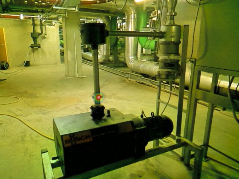
A leak in a vacuum pump in a plant room

5. Measurement strategy: distance, angle of view and frequency window

1.Carry out the measurement under actual operating conditions if the leak only occurs under vacuum.
2.Start at a short distance, as the signal is often weaker than with compressed air leaks.
3.Use FFT or a frequency window to reduce interference in the ultrasonic range.
4.Scan potential leaks from several angles, as gaps and cracks can emit sound in a specific direction.
5.Where cladding is closed, use open areas or gaps; do not measure through Plexiglas or closed surfaces.
6.Always check hotspots in the context of the system: prioritise vacuum components and sealing points, and critically assess reflective surfaces.

6. Limitations of the method

Differential pressure determines the signal strength. The greater the pressure difference relative to the ambient pressure, the stronger the ultrasonic signal at the leak. As a practical lower limit, a value of around −300 mbar relative (approx. 700 mbar absolute) should be maintained; below this, the leak becomes more difficult to detect acoustically.

Material transport can cause interference. If the vacuum system is conveying solids such as injection-moulding granules, the impact of the particles against the pipe wall can generate broadband ultrasound that masks the leak signal. As this falls within the same frequency range, shifting the frequency window is only of limited help – therefore, testing should be carried out under vacuum without simultaneous material conveyance.

Very small leaks may fall below the acoustic detection limit – or be masked by spatially close, stronger ultrasonic sources. If this cannot be resolved even by reducing the measurement distance, supplementary leak testing methods may be necessary.

Ultrasonic measurement quickly localises typical leaks during operation, but does not replace every highly sensitive leak test in the micro-range.

Further reading:Compressed air leak detection despite ultrasonic interference sources

7. Benefits for users

ProblemUltrasonic solutionAdvantage
Vacuum reaches setpoint only slowlySystematically inspect sealing points using ultrasound.Faster identification of potential sources of external air ingress.
Pump load increasesLocalise and prioritise leak points.Lower pump load and more stable operation.
Process quality fluctuatesTest seals and chambers under real-world conditions.Less external air ingress and more stable process conditions.
Leak in hard-to-reach areasMeasurement from a safe position or across open areas.Less dismantling required and faster inspection.