1. How does an ultrasound camera work for leak detection?

An ultrasound camera detects high-frequency sound waves generated at leak points by escaping compressed air, escaping process gases or the inflow of ambient air in vacuum applications. A microphone array uses the microphone signals to perform the calculation of the direction of the sound source and superimposes the result as a coloured heatmap onto a video image.

The method operates passively: the camera does not require a test gas such as helium or formier gas, but instead detects the acoustic energy generated by turbulence at the leak site. This enables leaks to be localised whilst the plant is in operation, without the need to shut down large sections of the plant, dismantle equipment or treat them with leak detection spray.

The technical benefit lies in the combination of acoustic localisation and visual identification. Users not only see that ultrasonic activity is present, but can also identify in the camera image which component, valve, hose, connection or section of pipe is generating the sound pressure. This reduces search time, prevents misinterpretations and simplifies the documentation of detected leaks.

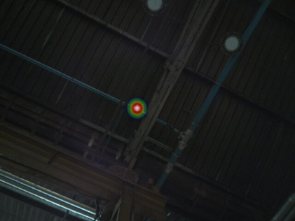
Ultrasonic camera detects a leak hotspot on a hard-to-reach factory ceiling

Example: Localising an ultrasonic source on a hard-to-reach hall ceiling. The hotspot marks the acoustic source in the camera image.

2. Why leaks produce ultrasound

In industrial leak detection, the distinction between audible sound and ultrasound is crucial. Most production noises fall within the audible, low-frequency range. Leaks in compressed air and gas pipes generate broadband turbulence with high-frequency sound components at small leak openings. Large leaks often generate audible sound as well; however, in production environments, this is frequently masked by machine noise.

Frequency rangeDescriptionSignificance in industry
Audible sound (approx. 20 Hz to 20 kHz)Frequency range that can be perceived by the human ear.Noises from machinery, engines, fans and speech typically fall within this range.
Ultrasound (> 20 kHz)A sound range inaudible to humans.Leaks, partial electrical discharges and other high-frequency events frequently generate ultrasonic components.
Target frequency windowFor the measurement of a selected frequency range within the ultrasonic spectrum.Enables the suppression of interference signals and the targeted detection of relevant ultrasonic sources.

The ultrasound generated by a leak is not caused by the gas itself, but by the turbulence that occurs as the gas escapes. The pressure difference, the geometry of the leak and the shape of the outlet opening determine the sound intensity and the frequency spectrum of the generated ultrasonic waves.

Higher frequencies offer better spatial resolution due to their shorter wavelength. However, as the frequency increases, atmospheric attenuation also increases, thereby reducing the achievable detection range.

The choice of measurement frequency therefore represents a trade-off between resolution, range and interference suppression. In many industrial applications, a frequency range around 40 kHz has proved to be favourable. In environments subject to interference, however, a different frequency window may yield better results.

Further reading: Leak detection despite interference sources and FFT
3. Why compressed air is the most important application

For CS INSTRUMENTS, compressed air is the primary application for ultrasonic leak detection. The reason for this is the direct link between leaks, consumption, compressor load and energy costs. Any unplanned air loss increases demand on the consumer side. If the leak is rectified, less air needs to be generated, dried and treated.

Finding leaks is the first step. Verifying the actual savings through consumption measurements taken before and after the repair makes this a robust efficiency measure. The ultrasound camera, LD 500, Leak Reporter, flow measurement and monitoring complement one another in the tasks of localisation, documentation, prioritisation and validation.

Continuous Improvement Process for Compressed Air Leak Management

4. How does the camera make the hotspot visible?

The acoustic map is generated using beamforming. The microphone array detects the incoming ultrasonic signals at defined positions. The system performs a calculation to determine the probable position of the sound source based on the differences in travel time and phase. A sound pressure value is determined for each pixel and superimposed on the camera image as a heatmap.

The heatmap is not a photograph of the leak, but a visualisation of the calculated sound source. By superimposing it onto the camera image, the hotspot can be clearly attributed to the component causing it.

Further reading: Beamforming explained simply

5. Coverage, frequency and limits

The detection range of an ultrasound camera is not determined by a fixed value. It depends primarily on the size of the leak, system pressure, frequency range, environmental interference, viewing angle and atmospheric attenuation. Large leaks can be detected from a significantly greater distance than micro-leaks.

Influencing factorEffect on detectionConsequences for users
Minimum differential pressureTypically at least approx. 250 to 300 mbar relative overpressure or underpressure.If the differential pressure is lower, the turbulence may be too weak to be detected reliably.
Minimum volume flow rateApproximately 0.03 to 0.05 l/min at a test distance of 3 m for reproducible detection.The value depends on the interference level, frequency window, sensor technology, leak geometry and distance.
Leak size / volume flow rateLarger leaks generate higher sound pressure.First identify large defects from a distance, then systematically move closer to smaller defects.
System pressure / differential pressureA higher differential pressure increases flow velocity and ultrasonic level.For micro-leaks, it may be advisable to carry out a measurement at a higher, but permissible, test pressure.
FrequencyHigh frequencies improve localisation accuracy but are more heavily attenuated in air.Test at medium frequencies over long distances; switch to free frequency windows in the event of interference.
Sources of interferenceProcess-related ultrasonic sources can mask leak signals.Use FFT, reduce the distance, shift the target frequency window and prioritise pressurised areas.
Angle of viewDirectional leaks do not radiate with equal intensity in all directions.Scan components from multiple spatial angles, particularly in the case of nozzle-type leaks.
Ultrasonic camera detects leaks in a production environment from a distance

For medium-sized leaks, measurement distances of around 20 m can be reliably achieved under practical conditions. In the case of large leaks, significantly greater distances can be achieved under favourable environmental conditions. However, the maximum detection range is significantly influenced by the sound pressure level of the leak, the frequency spectrum of the ultrasonic signal, atmospheric attenuation and the signal-to-noise ratio. Figures of up to 120 m therefore represent a maximum guide value.

6. Compressed air, industrial gases and vacuum: an overview

Acoustically, it is not the type of gas itself that is detected, but rather the ultrasonic waves generated by the gas escaping. Whether a leak can be detected depends primarily on the pressure difference, the geometry of the leak, the flow rate, the measurement distance and the environmental conditions. The type of gas, on the other hand, is mainly relevant for the economic, safety-related and quality-related assessment of the leak.

MediumBrief assessmentFurther information
compressed airMain application relating to energy and efficiency. Leaks increase the base load and compressor workload.Compressed air leak detection whilst the system is running; demand side before supply side
Nitrogen, argon, carbon dioxide, oxygenAcoustically detectable where there is sufficient differential pressure and turbulent flow. Assessment based on media costs, process stability and safety.Testing technical gases using ultrasound
HeliumLarger localised leaks can be detected acoustically. Helium leak detection technology remains relevant for highly sensitive micro-leak tests.Testing technical gases using ultrasound
methane Acoustically detectable only at sufficient pressure and with turbulent outflow. Ultrasonic testing is no substitute for gas detection technology.Testing technical gases using ultrasound
VacuumPossible, but more challenging: ambient air flows into the system, and the signal is often weaker.Detecting vacuum leaks using ultrasound

7. Common problems: sources of interference, reflections and micro-leaks

Many production noises fall within the audible range. However, plant components can also generate ultrasonic signals, for example pneumatic actuators, conveyor systems, presses, friction points, blow-off nozzles, partial discharges or other leaks. Using FFT analysis and the selection of a suitable frequency window, such sources of interference can be identified and specifically filtered out.

Reflections occur on hard surfaces such as glass, Plexiglas, concrete, sheet metal or smooth machine casings. A hotspot on a wall, floor or other surface may therefore also be caused by an echo. The most important step in the test is to change the viewing angle: a real sound source remains localised at the component causing it, whilst a reflection shifts or disappears.

Further reading: Leak detection despite interference sources and FFT

Ultrasonic camera detects a leak in a packaging machine through an open gap rather than through Plexiglas

A leak in a packaging machine with a plexiglass casing. The measurement is not taken through the closed surface, but via an open gap with a direct sound path.

8. Which CS INSTRUMENTS solution is the right one?

TaskSuitable solutionClassification
Making ultrasound audibleLD 500 / LD seriesConventional leak detection using the heterodyne method, with accessories and close-range sensitivity.
Visually locating leaksUltraCam / LeakCam 600A hotspot in the camera image facilitates localisation and documentation.
Complex systems, longer distances, multiple sourcesLeakCam 60064 microphones, Power Beamforming, FFT and frequency management.
Document leaks and track repairsCS Leak ReporterReports, prioritisation, repair status and potential savings.
Validate savingsFlow measurement, DS 500, CS NetworkCompare consumption before and after the measure.
Assess generationCMM 500, specific outputOptimise the supply side only after demand-side adjustments have been made.