
VA 500 - Flow meter for compressed air and gases
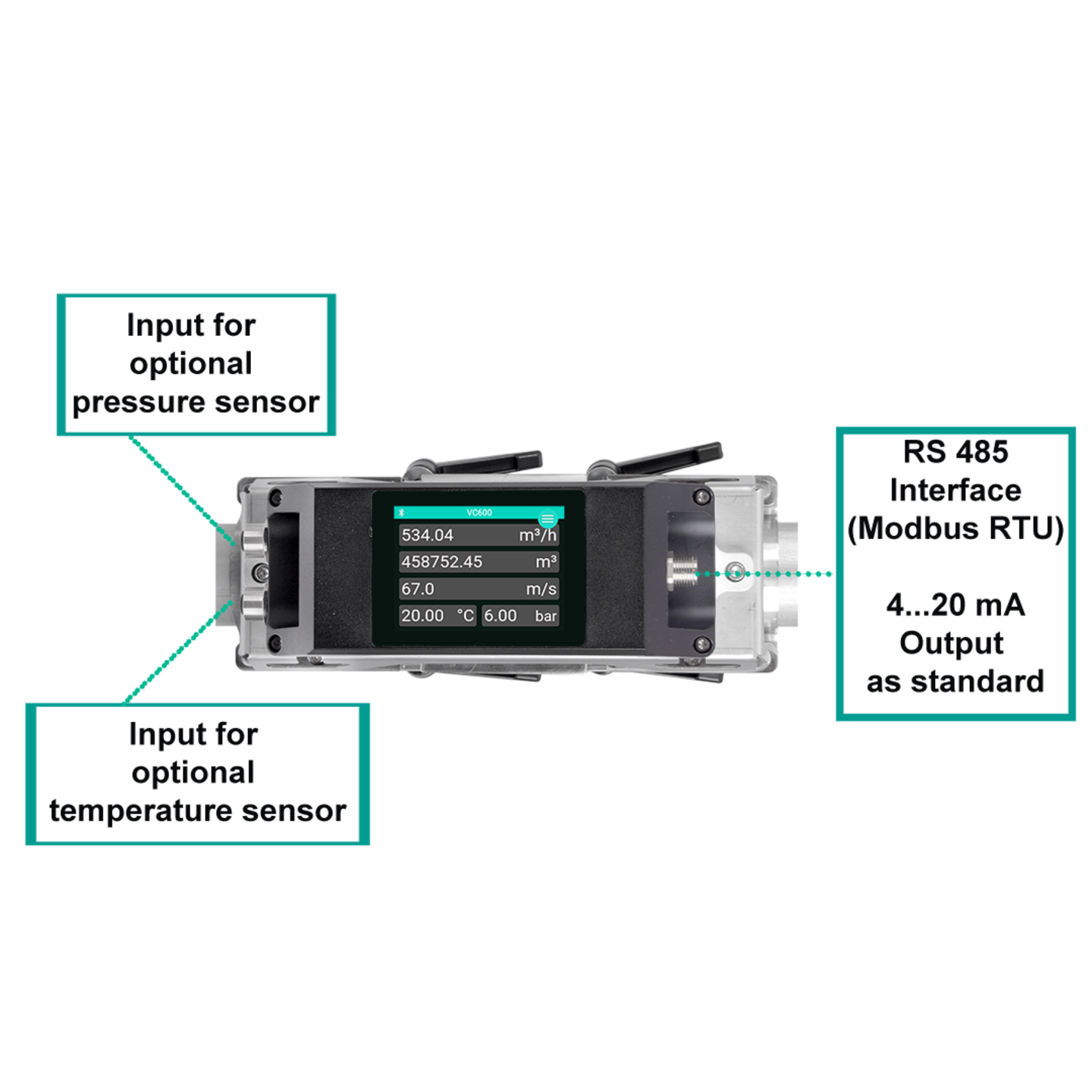
RS 485 Modbus interface, 4...20 mA Analogue output, Pulse output integrated as standard.


Consumption measurement shows the quantities required by individual machines, departments or production lines, and how compressed air consumption is distributed throughout the day. This allows costs to be allocated internally according to consumption and used as a key performance indicator in energy management in accordance with ISO 50001 or in energy audits in accordance with EN 16247-1. The base load at the end of a shift indicates leaks and continuous consumers; measurements taken before and after a measure is implemented show how effective it has been. Load profiles showing peak and base loads also provide a data foundation for planning pipework, dryers and compressors. The VC 600 enables this consumption measurement even on existing pipework without any intervention in the pipework, as it measures from the outside.
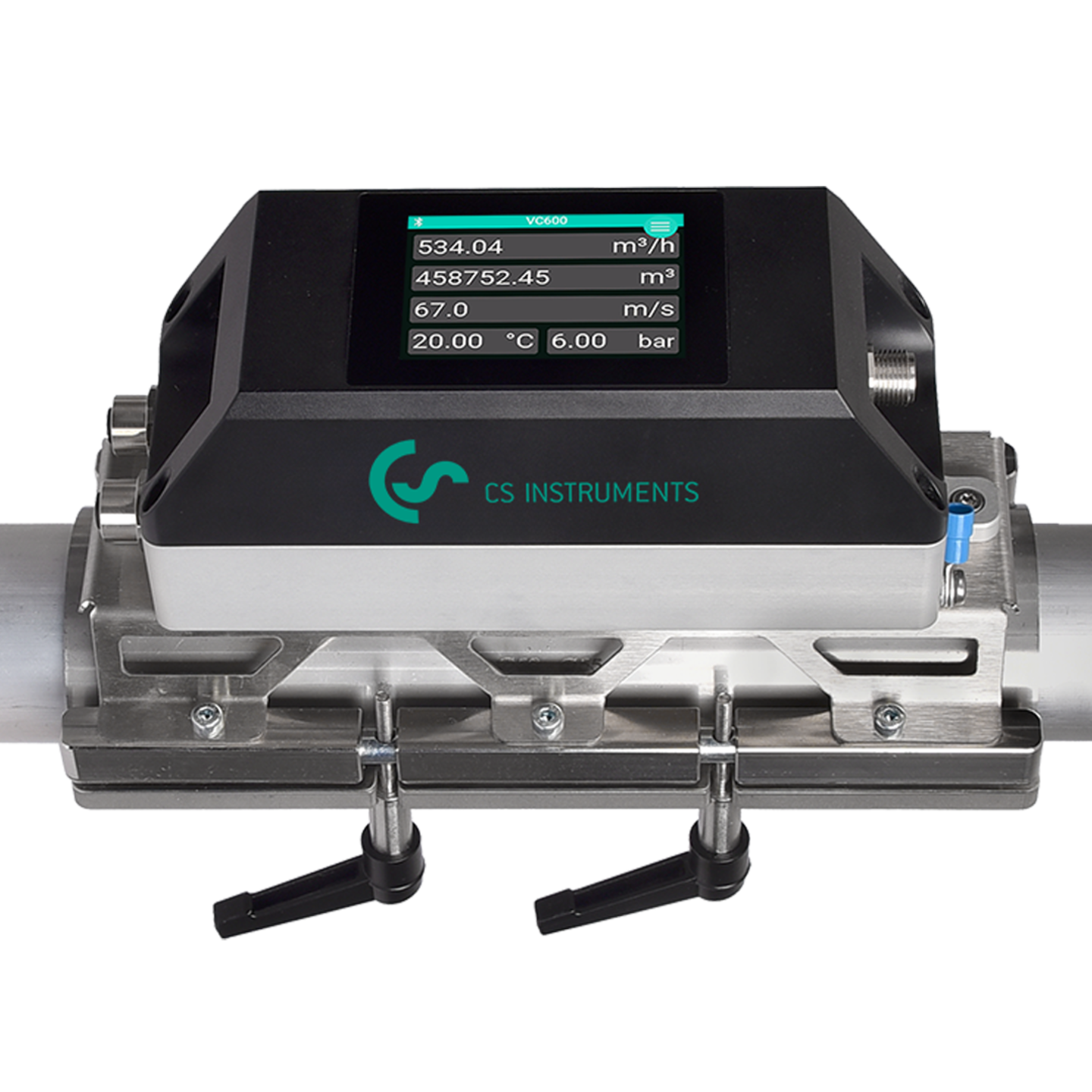
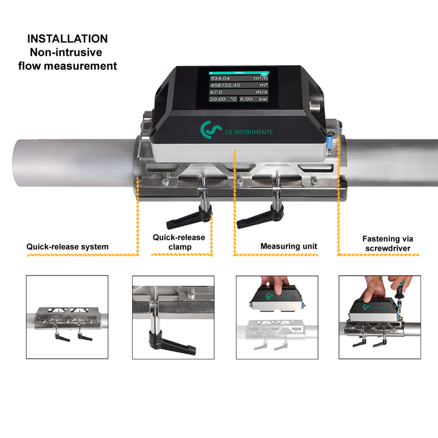
The VC 600 is an ultrasonic flow meter based on the time-of-flight principle. ‘Clamp-on’ means that the sensor measures from the outside – without any intervention, often referred to as non-invasive. Two piezo transducers in the sensor unit alternately transmit ultrasonic signals through the pipe wall, both with and against the flow. The flow velocity is calculated from the difference in transit time; the volume flow is then derived from the velocity and the pipe cross-section. The difficulty with gases is that they conduct sound significantly less well than water; consequently, only a small proportion of the acoustic energy passes through the pipe wall into the gas. The VC 600’s sensor unit is therefore calibrated to the pipe wall thickness, ensuring that a sufficient signal is received even at low pressures; from 3 bar(g) upwards, the device measures reliably in metal pipes. Interference noise travelling through the pipe wall is absorbed by the damping mat in the quick clamp system.
The quick clamp system, made from 1.4404 stainless steel, consists of two half-shells with an integrated damping mat. It is placed around the pipe at a paint-free section and secured alternately using the four quick-release clamps; the clamps pull the half-shells evenly against the pipe so that the transducers make full contact. The sensor unit is then fitted and secured with two M4 screws. Ultrasonic gel or coupling pads are not required; the distance between the transducers is determined by the sensor unit, and no more than a screwdriver is needed.
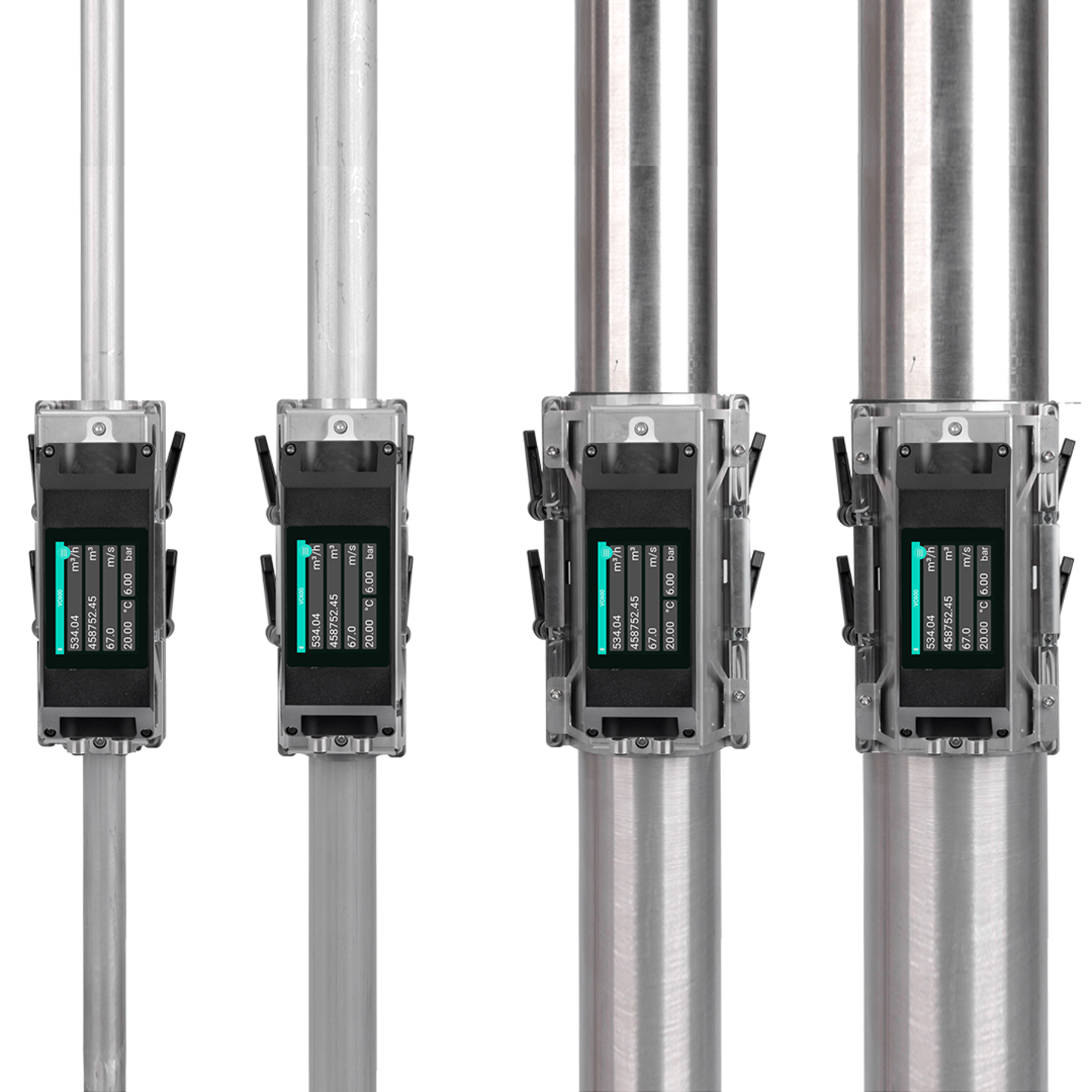
The quick clamp system is selected according to the outside diameter of the pipe, in ten sizes ranging from 25 to 90 mm (¾″ to 3″). The sensor unit is available in two versions, designed for wall thicknesses of 1.5 to 2.2 mm and 2.2 to 5.0 mm; both fit all sizes of the quick-clamp system. Anyone wishing to measure several pipe sizes therefore only needs additional quick-clamp systems, not a second device. The outside diameter is the decisive factor, not the nominal diameter: A pipe with a nominal diameter of 50 mm measures 60.3 mm, a ‘50’ aluminium pipe measures 50 mm, and a stainless steel pipe in accordance with DIN EN 10357 measures 53 mm. Consequently, only the quick clamp system includes the pipe size code in the order reference.
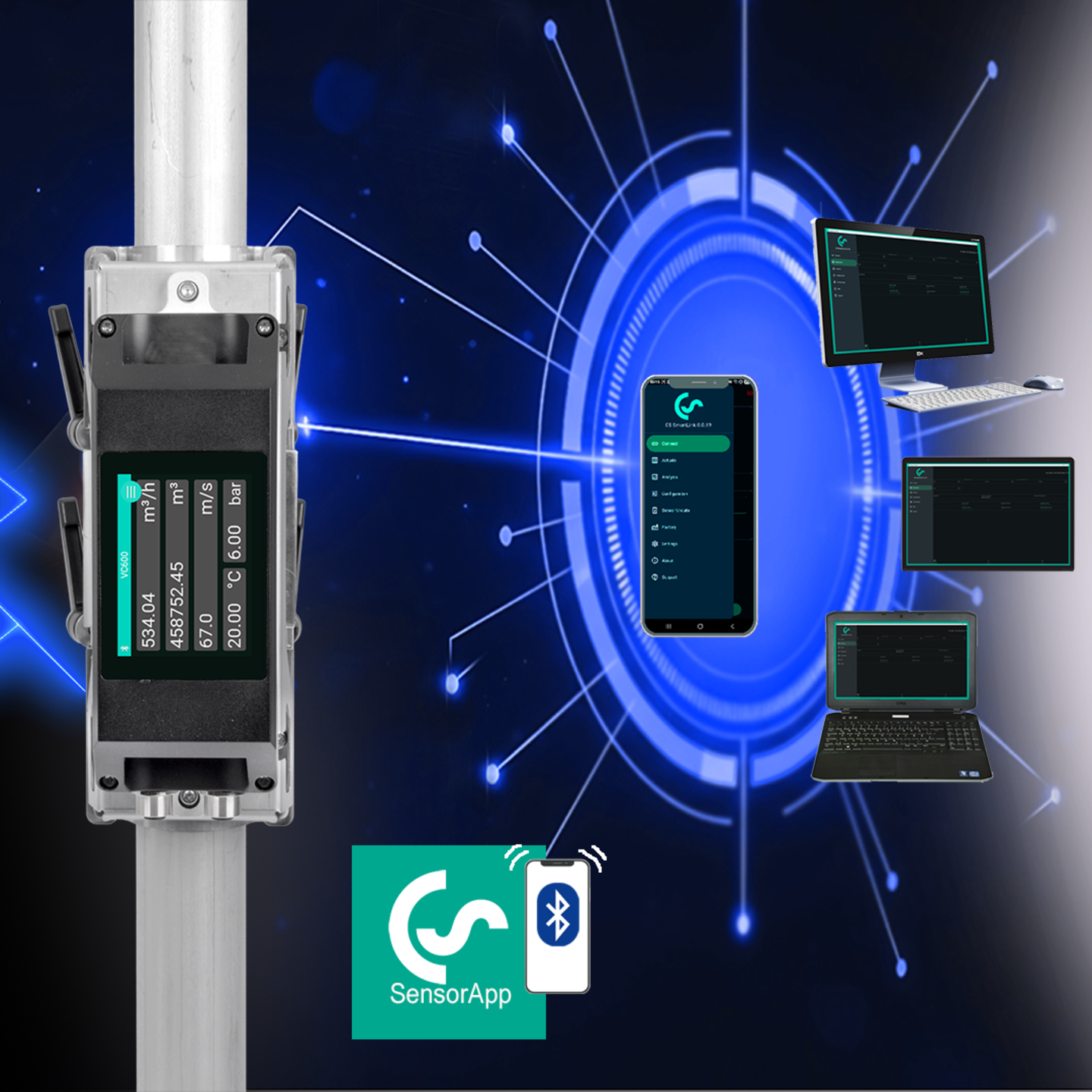
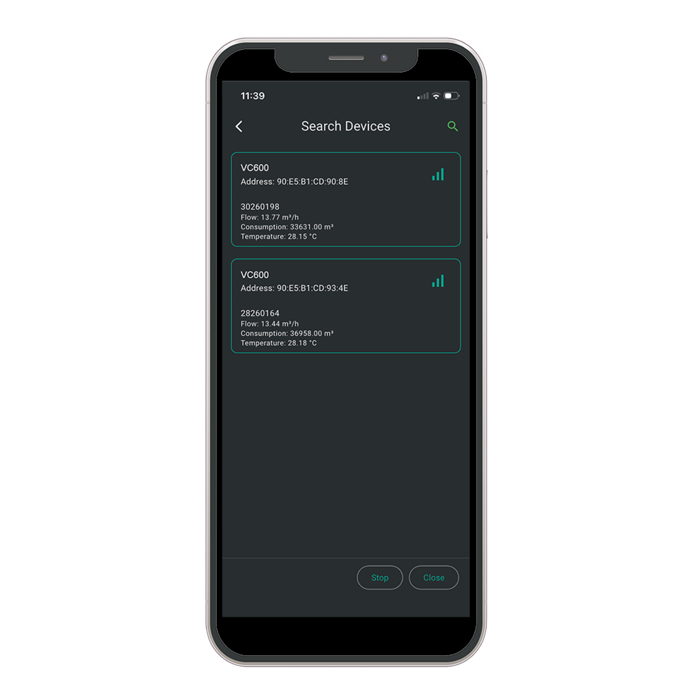
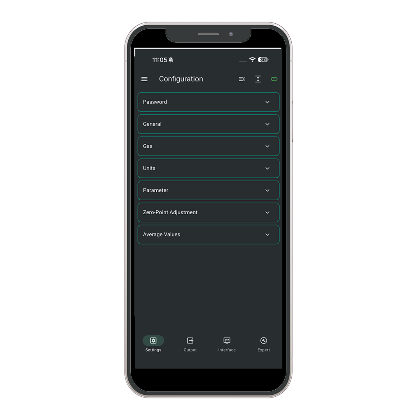
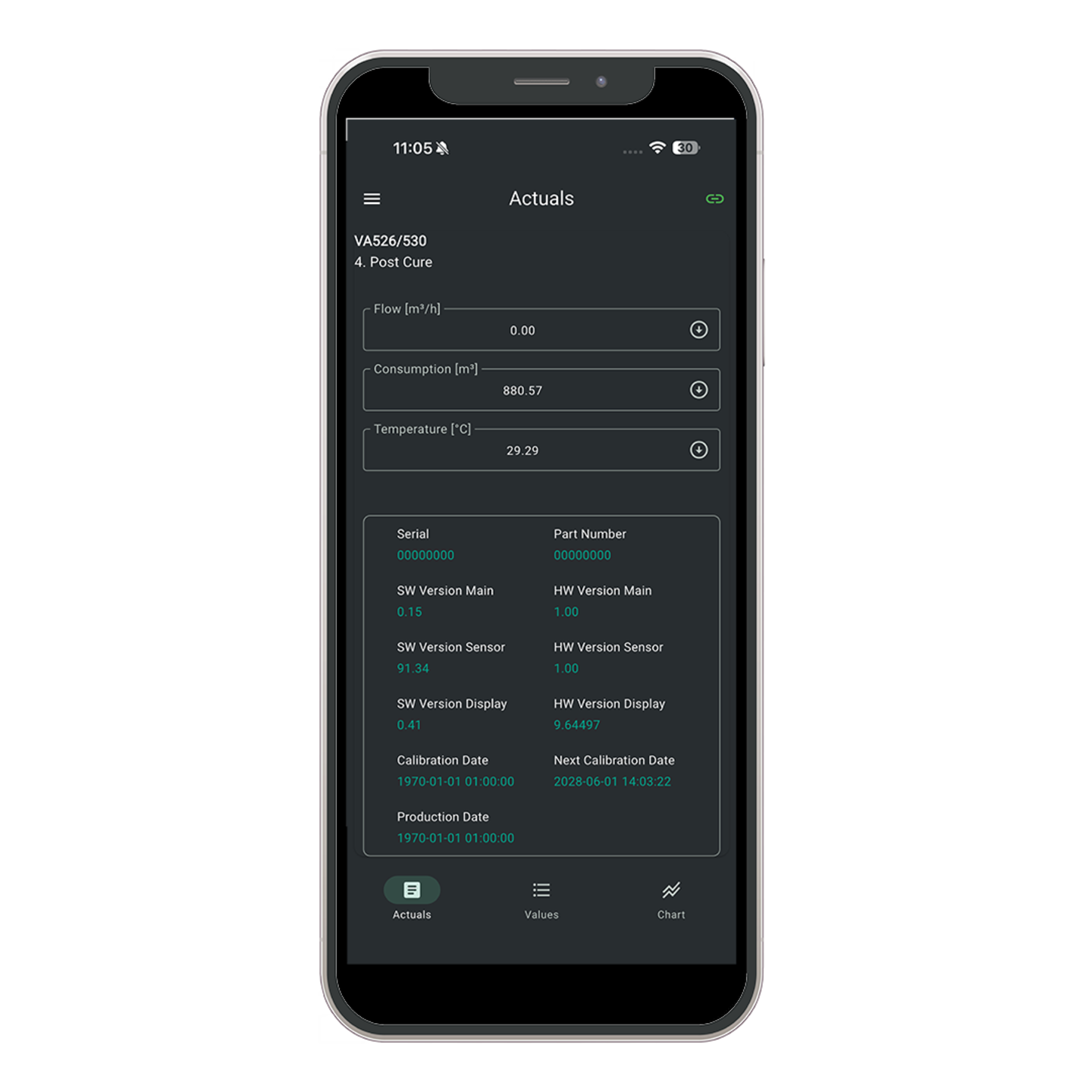
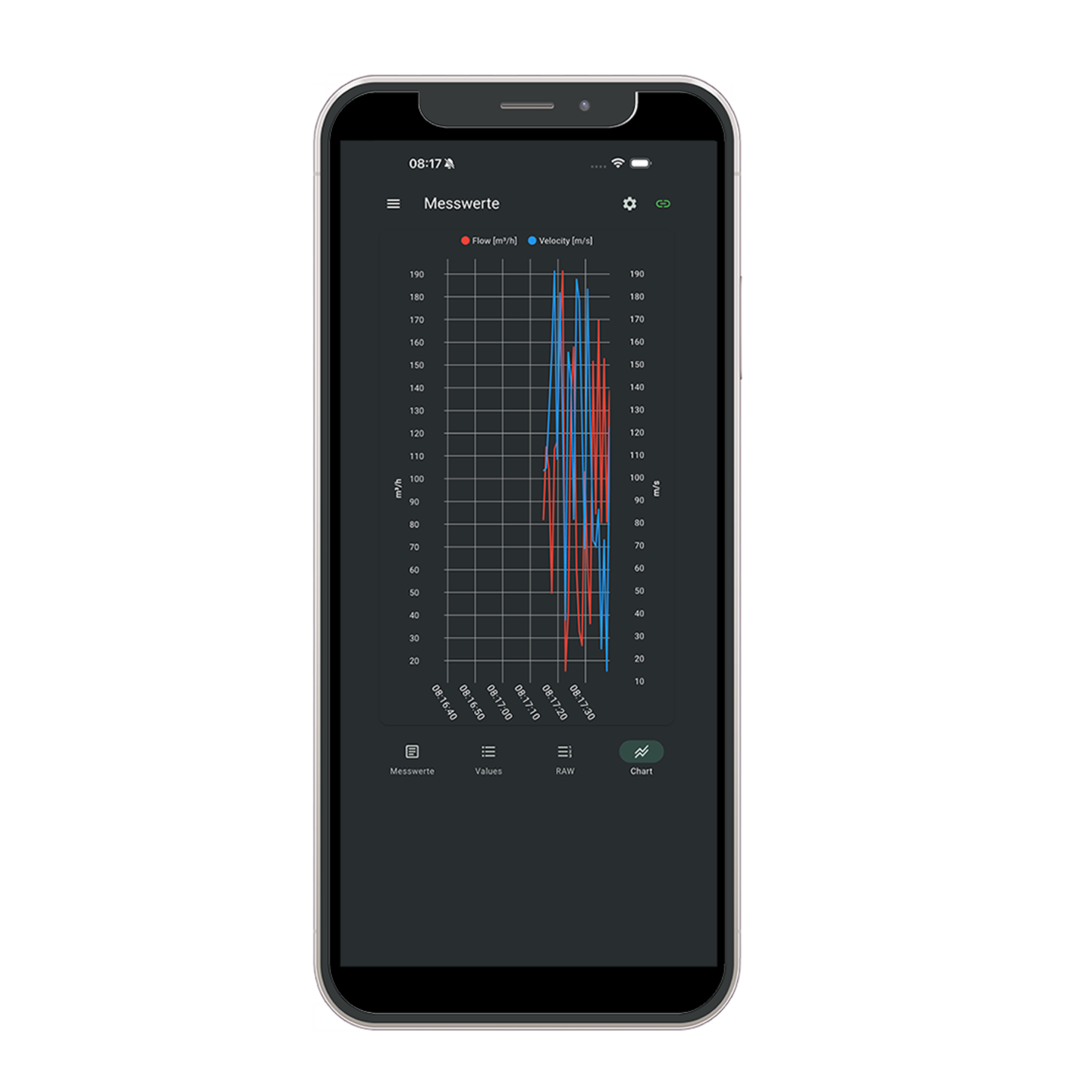
A set-up wizard guides the user through entering the inner diameter, wall thickness, pressure and temperature; pressure and temperature can be fixed values or continuously supplied by external sensors. Finally, the wizard checks the signal quality and confirms it. The VC 600 automatically converts the data to the selected reference conditions – ex-works in accordance with ISO 1217 – and, as a compressed air meter, totals the consumption; the CS SensorApp displays live values and trends via Bluetooth.
Typical points of measurement for retrofitting include the supply line behind the dryer, branch lines to halls or cost centres, the supply line to a machine with conspicuous consumption, and high-pressure lines behind a booster; nitrogen consumption can also be allocated to individual points of consumption in this way. The pipe remains closed; no new connection coming into contact with the medium is created. The measured values are transmitted via the selected interface to a chart recorder such as the DS 500 or directly to the energy management system.
| Feature | VC 600 |
| Measuring principle | ultrasonic transit-time difference, clamp-on |
| Measuring range | 0.08–20 m/s (F1); 0.08–25 m/s (F2) |
| Accuracy | ±1.5 % of reading ±0.3 % of full scale |
| Pipe outer diameter | 25–90 mm (¾″–3″); larger nominal sizes on request |
| Wall thickness | 1.5–5.0 mm (measuring unit B1 1.5–2.2 mm, B2 2.2–5.0 mm) |
| Pipe materials | steel, stainless steel, aluminium |
| Line pressure | from 3 bar(g); upper limit set by the pipe, not by the sensor; suitability for high-pressure lines assessed from pipe and operating data |
| Gases | compressed air, nitrogen; others on request |
| Calibration | factory calibration with certificate; standard via gas constant (D1), true gas calibration for the selected gas (D2); recalibration by sending in the measuring unit |
| Temperature | line −30 … +80 °C, ambient −20 … +70 °C |
| Reference conditions | ISO 1217 (20 °C, 1,000 mbar, dry), DIN 1343 normal conditions for Nm³ (0 °C, 1,013.25 mbar), 15 °C/981 mbar, 15 °C/1,013.25 mbar (gas-industry base, ISO 13443) |
| Inputs | pressure 4–20 mA or Modbus RTU (PTS 500); temperature Pt100/Pt1000 or 4–20 mA |
| Outputs per version | I1: 4–20 mA + RS 485 Modbus RTU · I2: 4–20 mA + IO-Link · I3: Ethernet with PoE, Modbus TCP + 4–20 mA + RS 485 · I4: M-Bus + 4–20 mA + RS 485 Modbus RTU; Bluetooth for the CS SensorApp |
| Display, memory | touchscreen; totaliser; data logger 50 MB (about 2 years at 10 min) |
| Supply, protection, location | 18–36 VDC, 7 W; IP 65; indoor use, not for explosive atmospheres (Ex areas) |
Examples for compressed air at 7 bar(g) and 20 °C, standard volume to ISO 1217, full scale at 20 m/s. The complete table for every clamping system is in the data sheet.
| Inner diameter | Measuring range at 7 bar(g) |
| 21.7 mm | 0.85–213 m³/h |
| 41.9 mm | 3.18–794 m³/h |
| 50.0 mm | 4.52–1,130 m³/h |
| 60.3 mm | 6.58–1,644 m³/h |
| 80.9 mm | 11.84–2,960 m³/h |
A thermal sensor protrudes into the pipe and therefore requires a ball valve or a measuring section; the VC 600 is mounted on the outside of the pipe. It measures the flow velocity across the pipe cross-section and converts this to standard volume using pressure and temperature; a thermal sensor measures the mass flow directly and therefore needs to know the type of gas.
Most clamp-on flow meters are designed for liquids. Gases conduct sound much less effectively, so a sensor unit is required that can transmit a strong enough signal through the pipe wall. The VC 600 has been developed for this purpose and measures flow in metal pipes from 3 bar(g) upwards.
The minimum pressure is 3 bar(g). The upper limit is not determined by the sensor but by the pipework, as the device is mounted externally and is not subjected to pressure. As the measuring range is specified in terms of actual flow velocity, the VC 600 measures high standardized volume flows at high pressures: At 40 bar(g) and an inner diameter of 50 mm, 20 m/s corresponds to approximately 5,800 m³/h, based on 20 °C and 1 bar absolute, using the ideal gas approximation.
All three, each with its own function. The outside diameter determines the quick clamp system; you measure it using a calliper or by calculating the circumference (circumference divided by 3.14). The wall thickness determines the version of the measuring unit – 1.5 to 2.2 mm or 2.2 to 5.0 mm – and is included in the calculation; if it is unknown, the CS 0495 thickness meter measures it from the outside of the fitted pipe. The inner diameter is calculated as the outside diameter minus twice the wall thickness. It determines the pipe cross-section, from which the VC 600 performs the calculation for volume flow and consumption, and must therefore be correct: In the case of a DN 50 steel pipe (60.3 × 3.6 mm), underestimating the wall thickness by just 1 mm distorts the volume flow by around 8 per cent. The nominal diameter alone is not sufficient; the pipe material and pipe standard help to determine the outside diameter and wall thickness with certainty.
In compressed air networks, a relative pressure sensor such as the PTS 500 or CS 16 is sufficient: The VC 600 converts a fixed air pressure value of 1,000 or 1,013.25 mbar to the absolute pressure required for the standard volume calculation. A change in air pressure of 30 mbar alters the standard volume at 7 bar(g) by only about 0.4 per cent. An absolute pressure sensor can also be connected and adjusted on the device.
This is because the pipe wall determines how much sound reaches the gas. The sensor unit is calibrated for a specific wall thickness range to ensure that a sufficient signal is received even at low pressure. One version covers 1.5 to 2.2 mm, the other 2.2 to 5.0 mm. Both fit all quick-clamping systems.
Part of the ultrasound signal travels further into the pipe wall and is reflected back at flanges, welds and bolted joints. The damping mat in the quick clamp system absorbs this structure-borne noise at the sensor unit. If a flange is situated close to the point of measurement or if the pipe is very rough, this can affect the signal. In such cases, damping clamps fitted upstream and downstream of the sensor – suited to the pipe size and no more than 50 mm from the quick clamp system – can help.
For steel, stainless steel and aluminium pipes with an outside diameter of 25 to 90 mm and a wall thickness of 1.5 to 5.0 mm. Aluminium pipe systems for compressed air with outside diameters of 25 to 80 mm fall within this range. The installation site should be free of paint, rust and weld seams.
±1.5 per cent of the measured value ±0.3 per cent of the upper range value, i.e. the same value as for the VA 550 and VA 570 thermal sensors in their standard versions. This is subject to the pipe data being entered correctly and the point of measurement complying with the installation conditions.
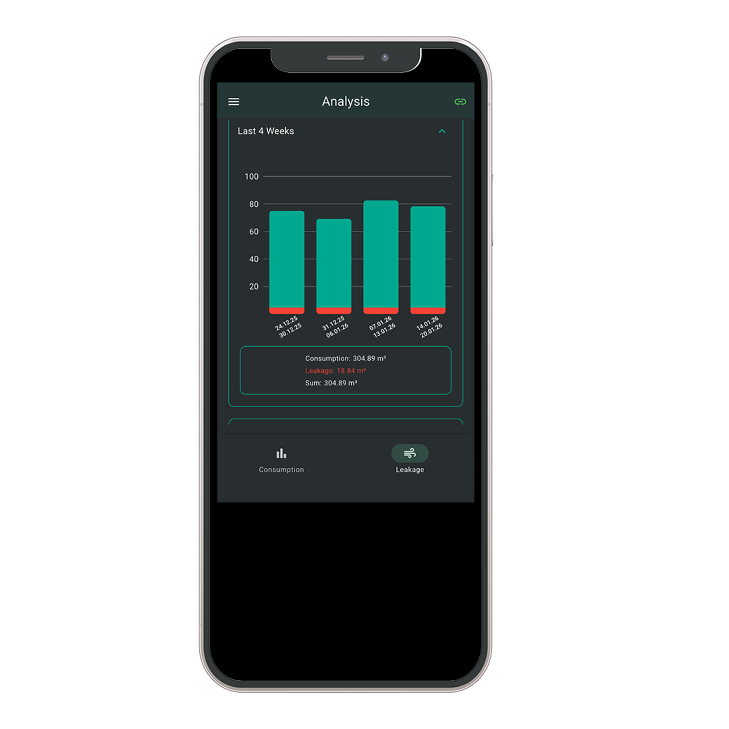
It displays this as the base load: any current remaining at the end of a shift is attributable to leaks and continuous consumers. Where residual quantities are very small, we will agree the measuring range and measurement uncertainty with you. The individual leak can then be located using the LD 500 leak detector or the LeakCam 600 acoustic camera.
Every VC 600 is calibrated on the CS INSTRUMENTS volume flow test bench prior to dispatch and is supplied with a calibration certificate. For recalibration, only the sensor unit needs to be sent in; the quick clamp system remains attached to the pipe.
You can easily create one or more configurations for this product.
When you add the product to the inquiry, all of your configurations will be automatically included in the inquiry.
Your current configuration
[[ error ]]
You have successfully completed your configuration.
Add it to your request now.
You have successfully completed your configuration.
You can now easily request it directly.
RS 485 Modbus interface, 4...20 mA Analogue output, Pulse output integrated as standard.

Insertion sensor for demanding industrial applications, comes with ATEX + IECEx approval for Ex zones or DVGW approval for use in natural gas.

for Compressed air / gases. New Digital electronics - improved Accuracy.

ATEX + IECEx approval for Ex zones and DVGW approval for use in natural gas.

Combines flow measurement, consumption monitoring, temperature measurement and, optionally, pressure and humidity/dew point monitoring in a single sensor.

Differential pressure sensor for measuring directly downstream of the Compressor in humid air up to +180 °C

Intelligent chart recorder with up to 12 sensor inputs. 7" colour display with touch panel.

2 in 1 sensor, measures Pressure and Temperature in the process.

for Measuring 0...10 and 0...16 bar with an Accuracy of max. 1% or max. 0.5% deviation.

for Measuring from 0...16 bar, RS485, G 1/2"

enables quick, easy and accurate measuring of the wall thickness of pipes.

Detects multiple leakages simultaneously with globally unique Power Beam Forming. 4th generation technology - also suitable for other gases. Helps to locate and repair leaks - including cost estimation and ISO 50001 documentation.