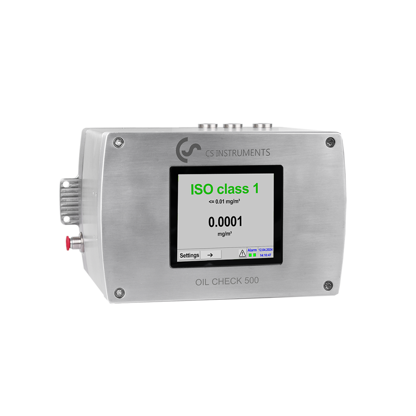
OIL CHECK 500 – Analyser for the continuous monitoring of gaseous oil concentrations in compressed air and gases

Understand the processing procedure, identify changes at an early stage, investigate deviations and ensure process quality.

Benefits at a glance:

  • Continuous data collection and control between regular laboratory tests
  • Early detection of deviations using trend data
  • Reliable measurements, supported by external verification, comprehensive calibration and internal diagnostics
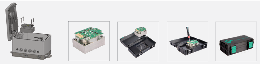
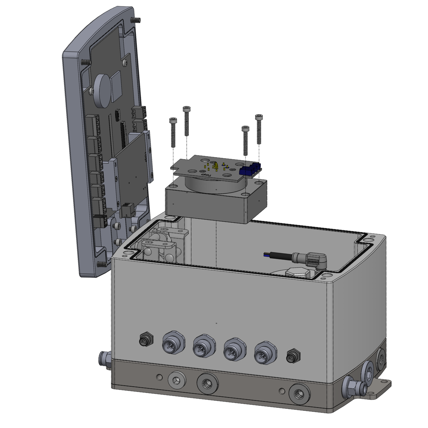
  • Ensured availability through a replaceable, pre-calibrated sensor module
to the request

The product has been added to the request.
to the request

Details

Description of the measuring device:

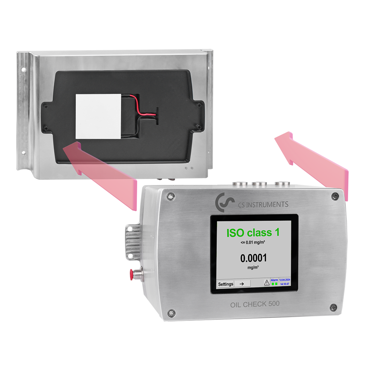
The OIL CHECK 500 continuously monitors the gaseous oil content in compressed air and other gases. The device identifies trends between regular laboratory tests and enables the investigation of any deviations.

This is always important whenever compressed air or other media may affect the product, the process or sensitive surfaces, such as in the following sectors:

  • Pharmaceutical industry
  • Food and drink industry
  • Electronics
  • Biotechnology and cosmetics
  • Technical gas supply systems

Related products

OIL CHECK 500 Portable

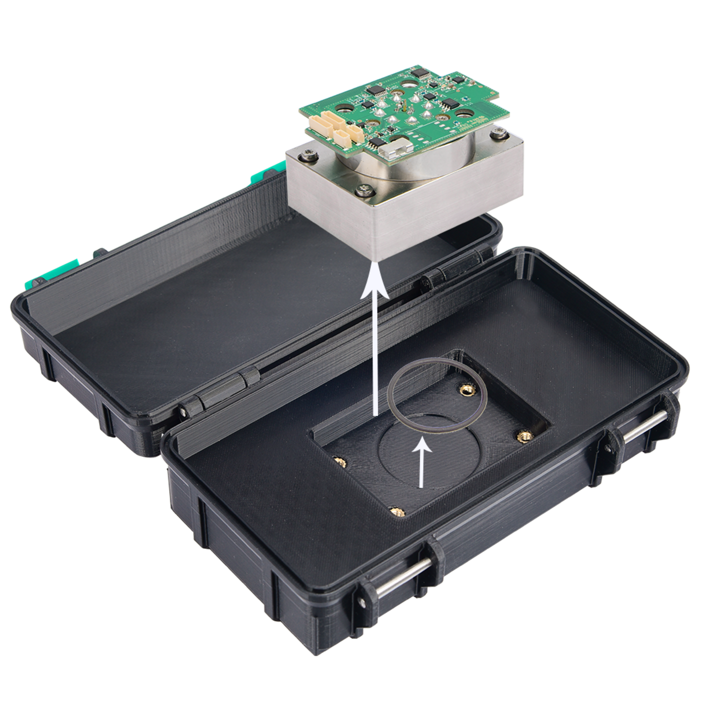
The Portable version of our monitoring system is supplied directly in a practical case.

More

Intelligent chart recorder DS 500 for compressed air and gases

Up to 12 optional sensors can be connected. 7" colour screen with touch panel.

More

CS Basic - 0554 8040

Data evaluation in graphic and table form - reading out of the measuered data via USB stick or Ethernet. License for two working places.

More

What online residual oil monitoring of oil-free compressors reveals

Three oil-free compressors. One manifold. A surprising observation. 
Oil-free compressors are often regarded as identical in terms of residual oil content.

If three compressors:

  • use the same intake air
  • supply the same compressed air network
  • are operated under the same environmental conditions

many people assume that they should have identical residual oil levels. In practice, however, this is often not the case.

Figure 1 shows a real-world measurement carried out using an OIL CHECK 500 on three oil-free compressors connected to a common manifold. All compressors operated under identical intake conditions. The same ambient air was compressed and fed into the same compressed air system.
Nevertheless, the trend in the residual oil levels clearly shows that each compressor behaves differently.

The value of high-resolution monitoring

The OIL CHECK 500 carries out several measurements per minute. This high measurement frequency reveals details that remain hidden in laboratory analyses. Rather than simply calculating an average value, the device continuously monitors the behaviour of the compressed air system.

This makes it possible to identify and distinguish between the following situations:

  • Compressor change
  • Load/idle cycles
  • Changes in operating conditions
  • Contamination events
  • Long-term ageing effects

The result is not just a figure. It is insight.

What the graph shows

  • Two compressors in operation
    Between approximately 13:25 and 14:00, Compressor A runs continuously, whilst Compressor B alternates between load and idle. The residual oil curve displays a characteristic undulation. The periodic fluctuations correspond exactly to the load/idle behaviour of Compressor B. Although both compressors are oil-free machines and operate under identical intake conditions, the OIL CHECK 500 can clearly distinguish the influence of the second compressor. This observation illustrates the sensitivity and temporal resolution of continuous residual oil monitoring.
  • Compressor A is switched off
    At approximately 14:02, Compressor A is switched off. Only Compressor B remains active. The residual oil trend changes immediately. The measured oil vapour concentration stabilises at a different level and exhibits a different characteristic behaviour. This change occurs in real time and is immediately visible.
  • Compressor C takes over
    At approximately 14:25, Compressor B is shut down and Compressor C begins operation. Once again, the residual oil profile changes. A third characteristic profile emerges. Although all three compressors are oil-free compressors operating on the same manifold and under the same intake conditions, each compressor exhibits its own residual oil behaviour.

Each compressor develops its own residual oil ‘fingerprint’

One of the most interesting observations during long-term monitoring is that compressors gradually develop their own characteristic residual oil profile.

Factors influencing this behaviour include:

  • Operating hours
  • Mechanical wear
  • Ageing of the seals
  • Internal contaminants
  • Maintenance history
  • Compressor design
  • Operating strategy

Even when compressors are nominally identical, their residual oil behaviour often differs. The OIL CHECK 500 reveals these differences. In many installations, experienced operators can identify which compressor is currently in operation simply by observing the residual oil trend. One might describe this as the compressor-specific residual oil ‘fingerprint’.

Why this is impossible with gas chromatography

Oil-free compressor technology significantly reduces the risk of contamination. However, it does not guarantee that all compressors will behave identically throughout their entire service life. As compressors age, subtle differences gradually emerge. These differences often go unnoticed during routine checks. Continuous monitoring detects them immediately.

This enables operators to:

  • compare compressors
  • To detect the effects of ageing
  • To identify abnormal behaviour
  • to optimise compressor operation
  • Detect contaminants before they become critical

The purpose of continuous residual oil monitoring is not simply to determine a numerical value. Its purpose is to understand what is happening within the compressed air system. The graph shown here illustrates a striking fact:

Three oil-free compressors operating under identical intake conditions do not necessarily exhibit identical residual oil behaviour. Only continuous monitoring can reveal these differences.

Conclusion

Gas chromatography provides information on how much oil has been collected during a measurement period.

The OIL CHECK 500 shows: In other words:

  • Which compressor was in operation
  • How it performed
  • How the residual oil content has changed over time
  • How the compressors compare with one another
  • How the system has developed over time

Gas chromatography provides a result.
Continuous monitoring can provide insight.

And this understanding enables operators to take action before contaminants become a problem.


About the author:

Danny Gillis, Eng.
Expert in compressed air since 1992

  • Thesis at Atlas Copco
  • R&D and test engineer at Atlas Copco for oil-lubricated compressors
  • Business Developer at Boge Compressors
  • Business developer for compressed air dryers and filters at Donaldson-Ultrafilter
  • Sales engineer for compressors in the transport solutions division at Gardner Denver
  • Reintroduction of two-stage, oil-free, double-acting piston compressors at AF Compressors
  • Compressor parts specialist at Burkert
  • Performance expert for compressed air and gases at CS INSTRUMENTS

Oil vapour measurement at a soft drinks manufacturer

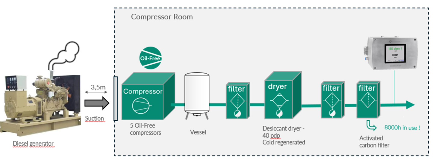
A soft drinks manufacturer operates a compressed air system fitted with five oil-free compressors. After passing through the compressors, the air flows through the following treatment components:

  • Air receiver
  • Pre-filter
  • Cold-regenerative desiccant dryer, which dries the compressed air to a pressure dew point of –40 °C
  • Supplementary filter
  • Activated carbon filter

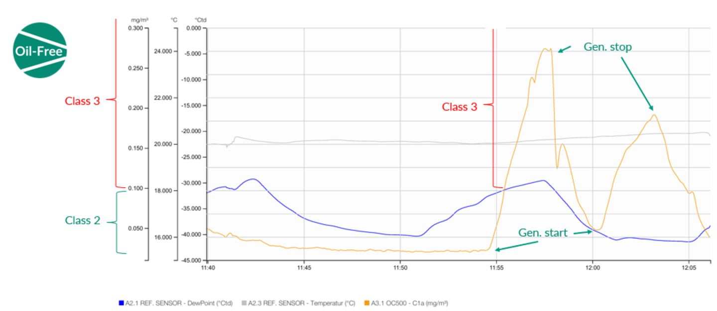
The oil mist measurements were carried out downstream of the activated carbon filter. Initially, the measured values remained within Class 2. However, the values then began to rise unexpectedly and reached Class 3. After a further decline, the values rose again and returned to Class 3.

Further investigations revealed that the increases in the measured oil mist concentration correlated with the start-up and operation of a diesel generator located on site. This suggested that the generator was likely contributing to the elevated oil vapour concentrations in the surrounding area.

At the time of the investigation, the activated carbon filter had already been in operation for around 8,000 hours. The activated carbon was therefore replaced and the filter refilled.

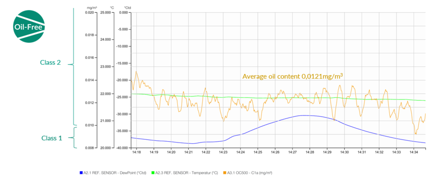
A subsequent follow-up measurement was carried out whilst the diesel generator was running. After the activated carbon had been replaced, the measured oil vapour levels remained consistently within Class 2, without any further peaks or fluctuations.
 
This case illustrates the importance of regular oil vapour monitoring in compressed air systems. Without oil vapour measurement, the depleted activated carbon filter would probably have gone undetected for much longer. Continuous or regular monitoring therefore helps to detect filter saturation at an early stage and contributes to reliable compressed air quality in sensitive production environments such as the drinks industry.

About the authors:

Samet Albayrak – Sales Engineer
Samet is an experienced engineer specialising in compressed air and gas systems. He has extensive practical experience in on-site audits and measurements.

asset_image


Onur Sallanbaş – Service Technician
Onur is an expert in compressors, gas treatment systems and measuring devices. Carrying out on-site measurements requires not only extensive experience but also a keen eye for external conditions, which he manages with ease.

asset_image

Why monitoring residual oil in compressed air is not a choice between gas chromatography and continuous online measurement

asset_image

  • It’s all about verification.
  • Whenever you need control.

When it comes to the measurement of residual oil in compressed air, the debate often boils down to a simple question:

Which method provides the best measurement?
However, that is not the most sensible question to ask.

A better question is:
Do you want to measure everything over a set measurement period, or do you want to continuously monitor the most relevant component?

This is the key difference between gas chromatography and the OIL CHECK 500. Gas chromatography can determine the total oil content in compressed air. It detects both oil vapours and oil aerosols. The OIL CHECK 500, on the other hand, continuously measures oil vapours.
At first glance, gas chromatography may appear to be the more comprehensive method. And from an analytical point of view, that is indeed correct. In real-world compressed air systems, however, comprehensiveness is only one aspect. Availability, continuity and response time are just as important.

Gas chromatography: measuring everything

Gas chromatography is a laboratory-based method for determining the total oil concentration in compressed air. It can detect both oil vapours and oil aerosols and is therefore ideally suited for verification and reference measurements.
For ISO 8573-1 Class 1, the ISO 8573-5:2025 standard stipulates a lengthy sampling period. In practice, this means that the measurement takes around five days. This is to ensure that sufficient air has flowed through the Tenax sampling tubes to determine with certainty whether the air meets Class 1 requirements or not.
If a system is tested for around five days a year, the remaining 360 or so days are not monitored using this method.

A great deal can happen during these days:

• A compressor may change its operating behaviour.
• Maintenance work may affect the system.
• Activated carbon may degrade.
• A filter element may be replaced.
• Environmental or process conditions may change.
• Temporary contamination may occur.

The results of gas chromatography indicate whether the compressed air met the requirements during the sampling time interval. They do not provide any information about what happened before or after this time interval. This is not a drawback of gas chromatography; it is simply in the nature of a laboratory-based testing method.
 
Gas chromatography answers the question: What was the total oil concentration during this sampling period?


OIL CHECK 500: continuous measurement

The OIL CHECK 500 answers a different question. It continuously monitors the oil vapour content in the compressed air. This distinction is important. The OIL CHECK 500 does not claim to measure every possible oil content. It measures the oil vapour content – and does so continuously. This is particularly relevant for high-quality compressed air in accordance with ISO 8573-1 Class 1 and Class 2.
At such low oil concentrations, the presence of significant oil aerosols is physically unlikely. This is not primarily an argument concerning filtration. It is an argument concerning phase behaviour. A comparison with water is helpful.
If the pressure dew point is significantly below the actual compressed air temperature, the presence of liquid water is not to be expected. The water is present as vapor. Similarly, at very low residual oil concentrations, oil aerosols are not the predominant problem. The relevant remaining fraction typically consists of oil vapor.

It is precisely this proportion that is monitored by the OIL CHECK 500. And it does so continuously. Not just for five days. Not as a one-off test in the laboratory. But every day of the year.

The importance of continuous monitoring
A periodic laboratory test can confirm that a system met the requirements during the sampling period. Continuous online monitoring shows whether the system remains stable in day-to-day operation.

That is the crucial difference.
Compressed air systems are dynamic. They are influenced by load, temperature, maintenance, ageing components, the condition of the adsorber and the operating profile. A system that functions well during a sampling period may nevertheless exhibit a temporary deviation later on.
Without continuous monitoring, such deviations may go unnoticed.
With the OIL CHECK 500, the operator receives immediate information as soon as the oil vapour concentration changes. This enables a rapid response, protects the process and documents the stability of compressed air quality over a longer time interval.
The OIL CHECK 500 is designed for continuous operation. Thanks to its design featuring replaceable sensors, recalibration can be carried out simply by replacing the sensor, ensuring that the monitoring system remains available throughout the year.
That is why the difference is not merely technical in nature. It is operational in nature.

  • Gas chromatography is used for verification.
  • The OIL CHECK 500 is used for monitoring.

Why the two methods complement each other
Gas chromatography and the OIL CHECK 500 should not be regarded as competing technologies.
They complement each other.
Gas chromatography is the ideal method for verifying the total oil concentration over a defined sampling period. It can be used to confirm and validate the results of an online monitoring system.
The OIL CHECK 500 then ensures continuous monitoring between these verification measurements.
In other words:
Gas chromatography confirms. The OIL CHECK 500 monitors.
Together, they form a much stronger quality assurance concept than either method on its own.
Gas chromatography provides independent reference verification.
The OIL CHECK 500 ensures continuous process reliability.

All or nothing?
The decision can be summarised quite simply.
Gas chromatography measures everything over a defined time interval.
The OIL CHECK 500 continuously monitors the most relevant component.
For ISO 8573-1 Class 1, gas chromatographic measurement in accordance with ISO 8573-5:2025 requires sampling over approximately five days. This provides a meaningful and reliable verification result.
However, this also means that, with a typical annual monitoring strategy, there are approximately 360 days without continuous monitoring using this method.
The OIL CHECK 500 closes this gap.
It continuously monitors oil vapour – the physically relevant residual oil fraction in very clean compressed air systems – and provides the operator with immediate transparency as soon as anything changes.

So the real question is not:
Which method is better?

The real question is:
Do you just want to know what happened during the verification period, or do you also want to know what happens during the rest of the year?

Conclusion
For reliable residual oil monitoring in compressed air, the best approach is not to choose between gas chromatography and the OIL CHECK 500.
The best approach is to use both.
Gas chromatography is used to verify and confirm the total oil concentration.
The OIL CHECK 500 is used for the continuous monitoring of oil vapours and to protect the process day in, day out.
Together, they offer both analytical reliability and operational safety.
Everything you need when you require verification.
Whenever you need control.

About the author:

Danny Gillis, Eng.
Expert in compressed air since 1992

  • Thesis at Atlas Copco
  • R&D and test engineer at Atlas Copco for oil-lubricated compressors
  • Business Developer at Boge Compressors
  • Business Developer for compressed air dryers and filters at Donaldson-Ultrafilter
  • Sales engineer for compressors in the transport solutions division at Gardner Denver
  • Reintroduction of two-stage, oil-free, double-acting piston compressors at AF Compressors
  • Compressor parts specialist at Burkert
  • Performance expert for compressed air and gases at CS INSTRUMENTS

PID+: Low cross-sensitivity to ethanol

Since the start of the COVID-19 pandemic, at the very latest, the sensitivity of photoionization detectors to ethanol has been a key factor in compressed air measurements. Ethanol is a component of many disinfectants and is used for cleaning in many industries.
At the same time, ethanol is not a contaminant that plays a role in compressed air treatment.

It is therefore important that photoionization detector-based measuring devices designed for use in compressed air treatment or media supply exhibit very low cross-sensitivity to ethanol.

Otherwise, an uncalibrated photoionization detector-based measuring device will quickly produce false-positive results, which will mislead the user.


PID+ – Low cross-sensitivity to water

Moisture on deposits in the ionisation chamber can lead to conductivity and thus to an energy flow, resulting in an incorrect measurement. This is particularly important when measuring oil vapours in compressed air. The dryness of compressed air is also a quality characteristic. Consequently, one must regularly expect fluctuations in the humidity of the measurement gas. On the one hand, compressed air is generally very dry, and changes in dryness are often not very significant. On the other hand, however, the oil vapour values determined by a photoionization detector are at the limit of what is possible with measuring technology, and a photoionization detector that has not been very carefully designed may exhibit cross-sensitivity to moisture, leading to a significantly distorted oil vapour reading.

Many users of this technology are aware of this. This relationship can be identified by superimposing a humidity curve onto the photoionization detector’s oil vapour curve. These curves should not correlate with one another, but should run independently of each other.

A photoionization detector designed to perform a measurement of gaseous oil components in compressed air should exhibit only very low cross-sensitivity to water.


External verification of measurement performance

In order to ensure transparency in media preparation or media supply, a measuring device must be suitable for this purpose. On the one hand, it must

  • accurately cover the entire measuring range and, on the other hand,
  • have sufficient Class 1 resolution.

To verify this, we collaborate with the Fraunhofer Institute IPM. The Fraunhofer Institute for Physical Measurement Techniques (IPM) is one of the leading institutes for industrial measuring technology. The department, headed by Prof. Dr Jürgen Wöllenstein, focuses on measuring devices for gas and process engineering. The gas laboratories affiliated with this institute and headed by Dr Benedikt Bierer possess the necessary expertise and technical facilities to verify the performance of measuring devices.

Test setup:

asset_image

Benzene is used as the test gas for the OIL CHECK 500. The certified gas mixture has a benzene concentration of 6.4 ppm. To generate the various concentration levels in the test, the test gas is diluted with Class 1 compressed air via two calibrated mass flow metres. To create conditions that are as realistic as possible, the dry (<80 °C dew point) Class 1 compressed air is humidified to a dew point of –11.8 °C. The flow is 0.5 litres per minute, and the pressure corresponds to atmospheric pressure.

1. Verification of the measuring range

The measurement is highly linear across a measuring range spanning three orders of magnitude. It therefore covers the entire measuring range from Class 1 to Class 3. This is an excellent result and qualifies the OIL CHECK 500 for carrying out indicative measurements in accordance with EN 8573-5.

Application note: Under practical operating conditions, the likelihood of oil aerosols or droplets occurring increases as early as Class 3. This increases the risk of contamination of the OIL CHECK 500.

2. Verification of the detection limit

ISO 8573-1 specifies an oil vapour concentration of 0.01 mg/m³ for the transition from Class 1 to Class 2. To monitor the compressed air treatment process or the media supply, a measuring device must have sufficient resolution to detect relationships within this range. Resolution does not refer to the number of digits on a measuring device’s display, but to the number of distinguishable measured values that a measuring device can actually record. The resolution of a measuring device is determined by the standard deviation of its noise. Typically, 3 standard deviations of a measuring device are used to determine its resolution. If the range of 0.01 mg/m³ is to be monitored, a measuring device requires a sufficient number of discrete measured values that it can actually distinguish. A measuring device that measures within Class 1 should have adequate resolution in this range.

The OIL CHECK 500 achieves a detection limit of 0.00075 mg/m³ at 3 sigma. Consequently, the OIL CHECK 500 can achieve a resolution of 13 independent measured values within Class 1. Based on a conservative assumption of 6 sigma for the detection limit, this results in a lower detection limit (LDL) of 0.0015 mg/m³, which corresponds to approximately 7 measurements.

The OIL CHECK 500 is therefore suitable for measurements as part of reference measurements in accordance with ISO 8573-5.

Calibrated where it matters

The most important factor for an accurate measurement is the correct calibration of the measuring system. The Class 1 limit specified in ISO 8573 is 0.01 mg/m³. This corresponds to a volume concentration of 2.5 ppb, which means 2.5 parts per billion. The OIL CHECK 500 is calibrated at two adjustment points within Class 1, precisely where it matters most. Calibration at a further seven points ensures that even high residual oil readings can be measured reliably.

Long-term measurement stability – forced pressure compensation

The key measurement points for a PID measuring device in compressed air are at the start of the measuring range, i.e. close to the zero point. Zero-point errors become less significant at higher measured values, but have a virtually full impact at the start of the measuring range. Photoionization detectors for compressed air therefore normally feature a function that corrects deviations at the zero point. To do this, the measuring devices require what is known as ‘zero air’, i.e. air that is free of the gases to be measured. Zero air is usually produced using catalysts or filters. Both methods are prone to error. The generation of zero air can deteriorate over time.

The result is that the supposed zero air may actually contain an increasing concentration of the gas to be analysed. During a zero adjustment, the measured signal is set to zero. However, if the zero air is actually contaminated with a gas concentration, a zero-point error is incorporated into the instrument. This error increases over time and with each adjustment carried out. This is not apparent to the user. To detect this, frequent external calibration must be carried out. This leads to increased costs, logistical effort and, over the course of the calibration process, often to missing measured values. The OIL CHECK 500’s forced-pressure compensation addresses this.

Forced-pressure compensation determines whether the zero air is truly free of the gases to be analysed. These measuring devices can specifically vary the pressure in the measuring chamber. Changing the pressure causes a change in concentration for the sensor:
Single pressure -> Single concentration
Double the pressure → Double the concentration
Triple pressure -> Triple concentration
If the zero air contains a proportion of the gas to be analysed, this results in a rising straight line. This means that no correction of the zero point should be carried out.

If no proportion of the gas to be analysed is present, the measured value remains unchanged.

Green light for a zero-point correction.

Self-test or diagnostic coverage

asset_imageThe OIL CHECK is used for the continuous monitoring of media quality. It is therefore important that it provides reliable measured values. For this reason, a wide range of internal checks have been implemented.
Over time, a measuring device may lose sensitivity due to various internal or external changes.
asset_image

To remain a reliable measuring device for the user within a very low measuring range, as specified by Classes 1 and 2, it must be able to assess its current resolution and issue a warning or indicate a need for maintenance in the event of an excessive loss of sensitivity.
This is important because it is not readily possible for the user to distinguish between a measured value and the noise produced by the instrument.

asset_imageIt is important to assess the intensity of the light source. This has a direct influence on the ionisation of the gas components being measured. In the OIL CHECK, this intensity is therefore continuously measured and evaluated.

In addition,

  • supply voltage
  • sensor voltage
  • gas temperature
  • Internal relative humidity
  • Intensity of the light source relative to the calibration (lamp intensity)

monitored.